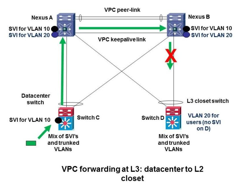
This network topology represents a Layer 3 forwarding model with Virtual Port Channel (vPC), connecting a data center to an access-layer switching infrastructure. The core of this design is a pair of Cisco Nexus switches (Nexus A and Nexus B) operating as a vPC domain, providing high availability, redundancy, and optimized traffic forwarding.
The topology includes a datacenter switch, which has an SVI (Switch Virtual Interface) for VLAN 10, and an L3 closet switch, which extends VLAN 20 to user devices but does not host an SVI for VLAN 20. This architecture enables efficient routing, segmentation of Layer 2 and Layer 3 domains, and ensures seamless failover in case of link or device failures.
At the core, Nexus A and Nexus B are connected via a vPC peer-link, which allows them to synchronize forwarding tables, MAC address learning, and configuration consistency. This ensures that both switches can participate in multi-chassis link aggregation, meaning downstream switches (Switch C and Switch D) can form a port-channel connection to both Nexus switches simultaneously.
Additionally, a vPC keepalive link is used for health monitoring between Nexus A and Nexus B, preventing split-brain scenarios where both switches operate independently in case of a peer-link failure.
For Layer 3 routing, both Nexus switches host SVIs for VLAN 10 and VLAN 20, making them the Layer 3 gateways for these VLANs. This setup ensures that inter-VLAN traffic does not traverse the access layer but is instead routed at the core, reducing latency and optimizing network performance. The datacenter switch (Switch C) also has an SVI for VLAN 10, allowing local devices to communicate within VLAN 10 efficiently.
However, VLAN 20 is only extended to the L3 closet switch (Switch D), which does not have an SVI for VLAN 20. This means VLAN 20 user traffic is forwarded as Layer 2 frames up to the Nexus switches, where routing decisions are made.
The diagram highlights a failure scenario on Nexus B, represented by a red cross. If this link to the L3 closet switch (Switch D) fails, all VLAN 20 traffic will be forwarded through the vPC peer-link to Nexus A, ensuring continuity. This behavior is a key benefit of vPC, as it allows uninterrupted traffic flow even in case of partial failures.
However, if the vPC peer-link itself fails while both Nexus switches are still operational, a split-brain scenario could occur, leading to inconsistent traffic forwarding and potential network instability.
From a design perspective, this topology provides multiple benefits. First, it enables Layer 3 forwarding at the aggregation layer, ensuring efficient routing without unnecessary traffic flooding at the access layer.
Second, it offers high availability and redundancy, as traffic can traverse multiple paths without disruption. The use of vPC eliminates the need for spanning tree protocol (STP) blocking, allowing full utilization of all links.